Cable Router Setup
In the Cable Router Setup dialog you can adjust how the cable router works. You can access the dialog in the following ways:
-
File > Environment > All library and project > [project] > Configuration > Plant Modeller > Cable Router Setup
-
Cabling tab > Cables group > Manager tool > Tools tab > Settings
The cable router settings are described below.
Cables
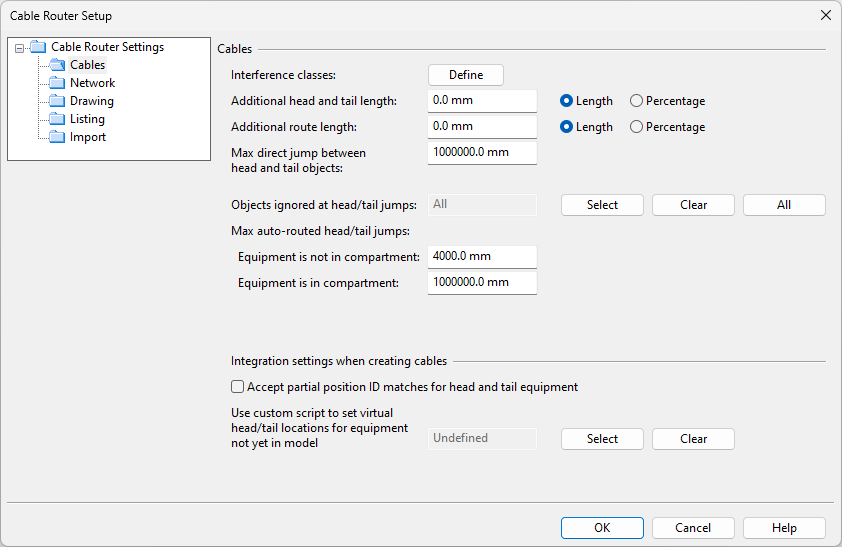
In the Cable Router Setup dialog, the Cables section includes the following settings.
-
Interference classes – Click Define to manage Cable interference classes.
-
Additional head and tail length – Specify the additional length to be added to both the head and the tail of the cable. The value can be entered either in millimeters or as a percentage. Cables can replace the default value with cable-specific values, as described in Set extra lengths.
-
Additional route length – Specify the additional length to be added to the route of the cable. The value can be entered either in millimeters or as a percentage.
Tip: For more information on cable lengths, see Cable length calculations.
-
Max direct jump between head and tail objects – Specify the maximum distance (mm) for the cable to go directly from the head equipment to the tail equipment. If the cables are not using the cable ways even though they should, try entering a smaller value here.
Note: If cables have already been routed, after changing this value you must recreate the cable routing network. This applies the change to the existing cable routes.
-
Objects ignored at head/tail jumps – In automatic routing, a head/tail jump might not be possible if a 3D object is blocking the route. Here, you can select object types that collision checking should ignore. Only applied when head and tail jumps are outside compartments.
-
Click Select to select the ignored object types with a COS query.
-
Click Clear to use collision checking for all object types.
-
Click All to ignore all object types, so that nothing is seen as blocking the route.
Note: 3D Spaces that belong to the host object of a cable network part, or to the head/tail equipment, are always ignored. Other 3D Spaces can block the jump if their object type is Cable Space, Insulation, Passage, or Service Space. Therefore, decide whether also these 3D Spaces should be ignored.
-
-
Max auto-routed head/tail jumps
-
Equipment is not in compartment – Specify the maximum distance (1000–10,000 mm) for an auto-routed cable to jump to head or tail equipment that is not inside a compartment.
-
Equipment is in compartment – Specify the maximum distance (100–100,000 mm) for an auto-routed cable to jump to head or tail equipment that is inside a compartment.
Note: The distance is calculated as the area length (dx+dy+dz) of the head/tail section, without extra tail lengths.
-
-
Allow creation of partial cable routes – Select this option to enable the cable route to start and end at Routing points. If this option is not selected, the start or end point must be a specified node in equipment or a virtual point. This option cannot be disabled if the model already contains partial cable routes.
-
Integration settings when creating cables
-
Accept partial position ID matches for head and tail equipment – Select this if the cable router should try to match the position ID of the head or tail equipment, which contains the sub-object part of the ID defined in CADMATIC Electrical, to a part of the position ID of the actual equipment in the 3D model. If this is not selected, the position IDs must be completely matching.
-
Use custom script to set virtual head/tail locations for equipment not yet in model – You can use a script to set virtual point coordinates to cable ends when the intended piece of equipment is already defined in an electrical diagram but not yet in the 3D model.
 Show/hide details
The script must contain the following function:
get_location_for_end_point(STRING epdOid, STRING tag)In this function, the first parameter is the OID of the diagram cable object (EPD object), the second parameter is the tag that specifies the cable end (either '.p9' for the head or '.pA' for the tail), and the return value should be the location of the cable end in the format 'x y z'. For example, '-5000 200 3500'.
Once the piece of equipment with the given position ID has been added to the 3D model, the Cable head status or Cable tail status column shows the value 'Equipment appeared', indicating that the change can now be applied to the cable.
-
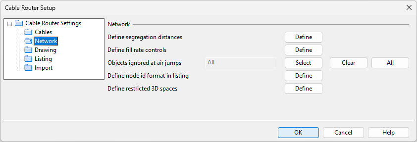
Network
In the Cable Router Setup dialog, the Network section contains settings that affect the cable routing network.
-
Define segregation distances – Click Define to specify the minimum distance between cables that belong to different interference classes. The distance is not applied to cable pipes. See Defining segregation distances.
-
Define fill rate controls – Click Define to specify a cost multiplier and a color for cable trays, conduits, and penetrations that reach a certain fill rate. See Defining fill rate controls.
-
Objects ignored at air jumps – In automatic routing, an air jump from one cable way object to another might not be possible if a 3D object is blocking the route. Here, you can select object types that collision checking should ignore, for example, to allow cables to pass through bulkhead insulation.
-
Click Select to select the ignored object types with a COS query.
-
Click Clear to use collision checking for all object types.
-
Click All to ignore all object types, so that nothing is seen as blocking the route.
Note: 3D Spaces that belong to the host object of a cable network part, or to the head/tail equipment, are always ignored. Other 3D Spaces can block the air jump if their object type is Cable Space, Insulation, Passage, or Service Space. Therefore, decide whether also these 3D Spaces should be ignored.
-
-
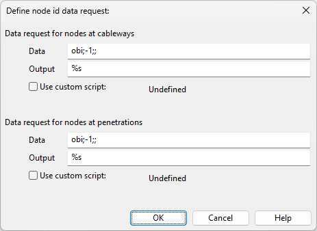
Define node ID format in listing – Click Define to open the Define node ID data request dialog. Here, you can define data requests that will be used when generating node IDs for cable ways and cable penetrations.
Alternatively, you can select the option Use custom script and select a custom script that generates the IDs. The custom script must be stored in the library or the project database (in Resources > Scripts), and must contain the following functions.
Copyget_user_defined_node_id(STRING crnNodeGuid) // Called when node is user defined and script is defined to be used.
get_penetration_node_id(STRING crnNodeGuid) // Called when node host is penetration object and script is defined to be used with penetrations
get_pipe_node_id(STRING crnNodeGuid) // Called when node host is piping part object and script is defined to be used.
get_cable_tray_node_id(STRING crnNodeGuid) // Called when node host is cable tray object and script is defined to be used.
get_stand_node_id(STRING crnNodeGuid) // Called when node host is a standard component and script is defined to be used.
get_other_node_id(STRING crnNodeGuid) // Called when node host is some other object and script is defined to be used -
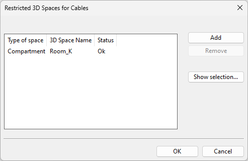
Define restricted 3D spaces – Click Define to open the Restricted 3D Spaces for Cables dialog. Here, you can specify that cables cannot pass through specific 3D spaces.
Important: If you add or remove 3D space restrictions, you must recreate the cable routing network as described in Recreate. Additionally, you must reroute any existing cables currently passing through a 3D space that has become restricted. This also applies to cables which could now have a more optimal route due to a previously restricted 3D space being made available.
-
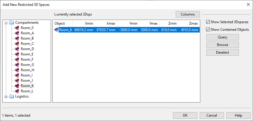
Add – Opens a containment browser where you can define the restricted 3D spaces by selecting them from the tree. Remove an unnecessary restriction by selecting it from the list and clicking Deselect.
-
Remove – Removes the selected 3D space restrictions from the list. For example, if the Status column shows the value 'Missing', the associated 3D space has been deleted from the model, and you should probably remove the restriction.
-
Show selection – Opens a containment browser that lists the 3D spaces that are currently defined as restricted. You can add and remove restrictions, if needed.
When there are restricted 3D spaces, the following occurs:
-
When you are routing a new cable, the cable cannot pass through a 3D space that is defined as restricted, unless an attribute overrides the restriction (see below). If an alternative route is not available, the cable cannot be routed at all.
-
When you select an existing cable from the Cable Manager dialog and the Show compartments option is selected, the restricted 3D spaces that are inside the bounding box of the cable route are shown in red color, as described in Views.
The restrictions are ignored in the following cases:
-
Head or tail equipment is located in a restricted 3D space. (Cables are allowed to start from and end in a restricted 3D space.)
-
Cable, cable material, or part size has the attribute 'Ignore Restricted Containments' (.IL) set to 'Yes'.
Note: Cable attributes override both cable material and part size attributes. If the cable has this attribute set to 'No', then it cannot go through the restricted space, regardless of how the attribute is set in the cable material or part size.
-
-
Cable area multiplier in mass penetrations – This factor multiplies each cable’s cross-sectional area in mass penetrations, ensuring there is enough room for the actual mass and the penetration is not filled entirely with cables. You can define any value between 1 and 10; the default is 2.5.
Drawing
In the Cable Router Setup dialog, the Drawing section contains settings that affect generating of drawings.

-
Annotation properties – Click Select to select the Annotation Properties to be used in cable drawings.
Fill rate views use the annotation properties as follows:
-
Text – Used for all text except for dimensions.
-
Polyline – Used for lines and boxes.
-
Circle – Used for cables.
-
Hatch – Used for the segregation areas between the cables.
-
Dimension – Used for dimensions.
-
-
Define data shown from cable trays – Click Define to specify a data request that shows data from cable trays.
-
Define data shown from cable penetration – Click Define to specify a data request that shows data from cable penetrations.
-
Define data shown from cables – Click Define to specify a data request that shows data from cables.
Create cable fill rate view into drawing
Listing
In the Cable Router Setup dialog, the Listing section contains settings that affect generating of listings.

-
Listing – Enter the separator character to use in node point lists. If not defined, the default separator character is space.
Import
In the Cable Router Setup dialog, the Import section specifies data mappings for importing cables from XML.
The mappings are case-sensitive, so we recommend that you copy–paste the values directly from XML data.

-
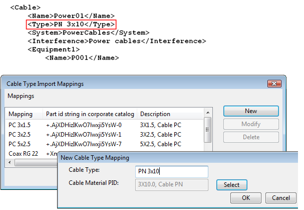
Define mappings for cable types – Click Define to specify mappings between cable type defined in import data and catalog size.
In the New Cable Type Mapping dialog, copy the Cable Type value from XML, and click Select to select the correct catalog part size. Note that there might be several type values for one catalog size.
-
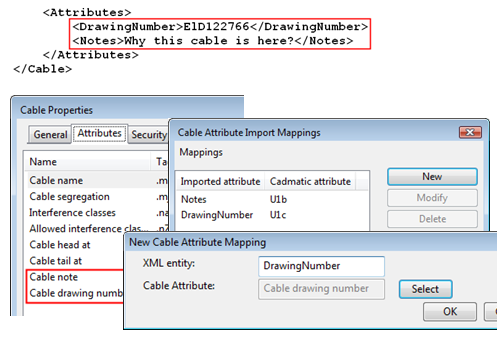
Define mappings for cable attributes – Click Define to specify mappings between XML and COS attributes.
In the New Cable Attribute Mapping dialog, copy the XML entity value from XML, and click Select to select the correct COS cable attribute.
-
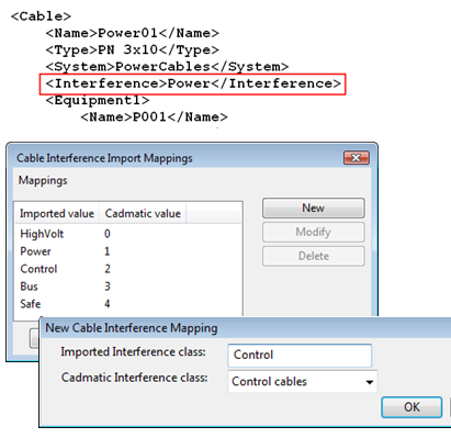
Define mappings for interference classes – Click Define to specify mappings between XML and CADMATIC interference classes.
In the New Cable Interference Mapping dialog, copy the Imported Interference class value from XML, and click Select to select the correct CADMATIC interference class.
Note: Every cable must have an interference tag.